Universal Logic Gate NAND
Logic Gate
In this tutorial we will learn about the Universal Logic Gate NAND.
Universal Gate
A universal gate is a logic gate which can be used to implement any other type of logic gates.
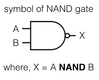
Logic Gate: NAND
The logic gate NAND takes two or more input and works as per the following truth table.
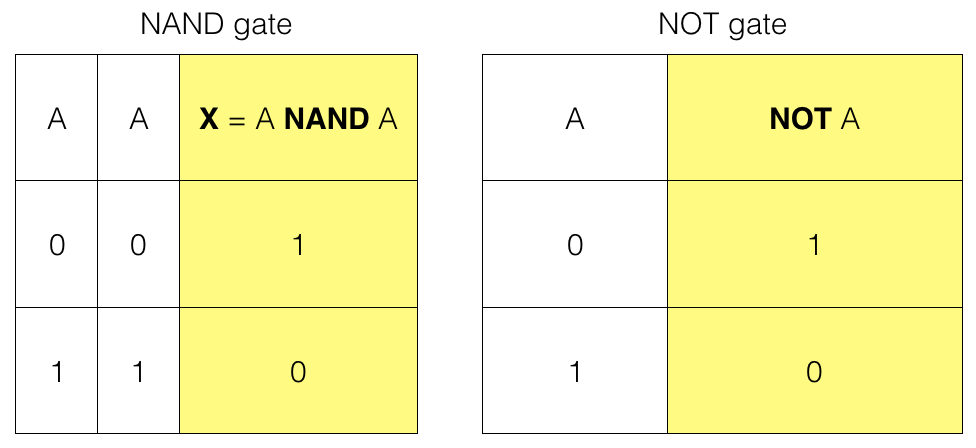
NAND gate truth table
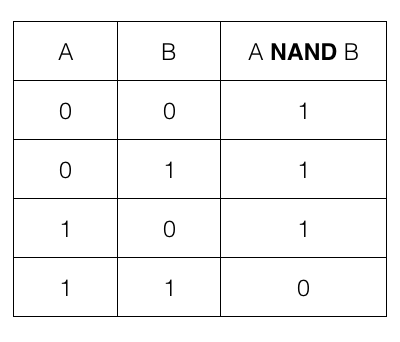
i.e., if both the input A and B are 1 or TRUE then the output is 1 or TRUE; otherwise it is 0 or FALSE
We can create AND, OR and NOT gate using the NAND gate.
NOT gate using NAND gate
We need only one NAND gate to implement a NOT gate. Let us first check a NOT gate and its truth table.
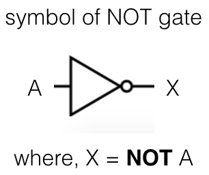
The logic gate NOT takes only one input and works as per the following truth table.
NOT gate truth table
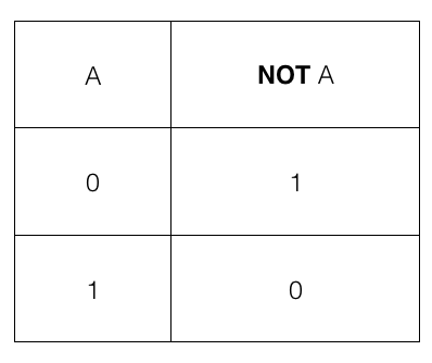
i.e., if the input A is 1 or TRUE then the output is 0 or FALSE and if the input A is 0 or FALSE then the output is 1 or TRUE
NAND gate to create a NOT gate
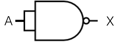
where, X = A NAND A
So, we feed A as input to the NAND gate. The output X is the final result which is same as a NOT gate.
So, we have a NOT gate using a NAND gate
AND gate using NAND gate
We need two NAND gates to implement an AND gate. Let us first check an AND gate and its truth table.
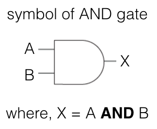
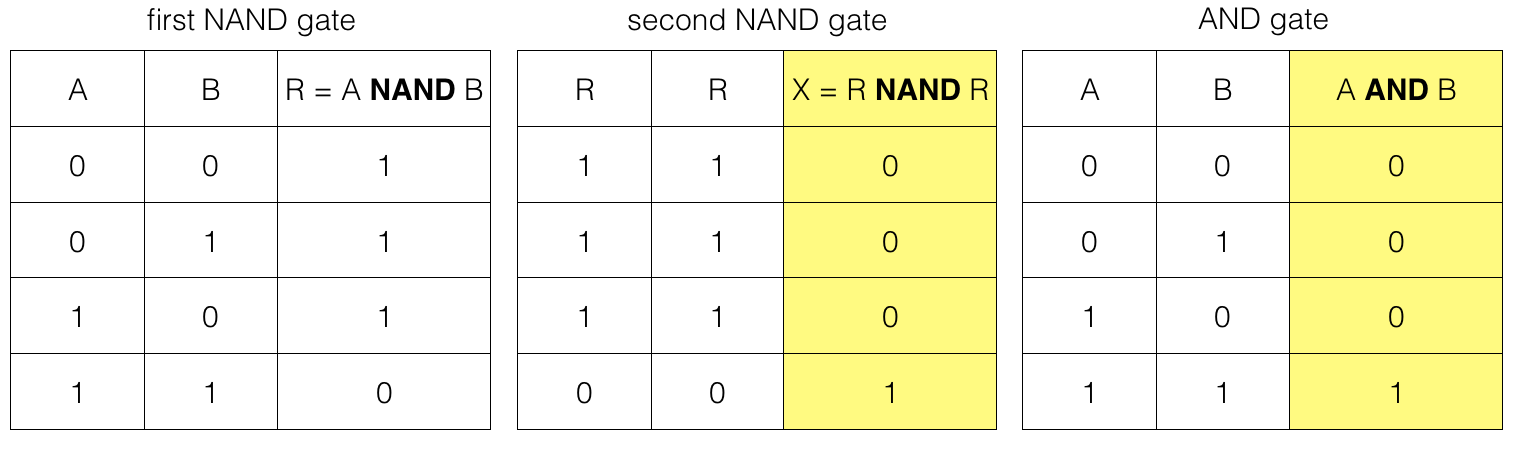
AND gate truth table
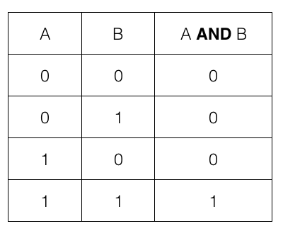
i.e., if both the input A and B are 1 or TRUE then the output is 1 or TRUE; otherwise it is 0 or FALSE
NAND gates to create an AND gate
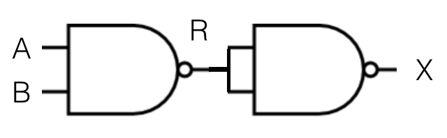
where, R = A NAND B
and, X = R NAND R
So, we feed A and B as input to the first NAND gate. The output of the first NAND gate R then becomes input for the second NAND gate. And the output of the second NAND gate X is the final result which is same as an AND gate.
Note! For the second NAND gate both the input is equal to R.
So, we have the result of an AND gate using two NAND gates.
OR gate using NAND gate
We need three NAND gates to implement an OR gate. Let us first check an OR gate and its truth table.
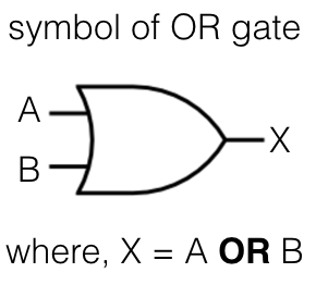
OR gate truth table
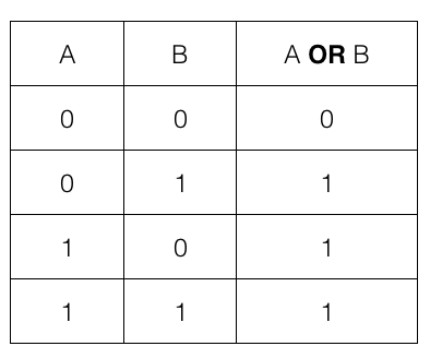
i.e., if any one of the input A or B is 1 or TRUE then the output is 1 or TRUE; otherwise it is 0 or FALSE
NAND gates to create an OR gate
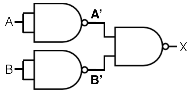
where, A' = A NAND A
and, B' = B NAND B
and, X = A' NAND B'
So, we feed A as input to the first NAND gate and B as input to the second NAND gate. The output of the first NAND gate A' and the output of the second NAND gate B' becomes input for the third NAND gate. And output of the third NAND gate X is equivalent to an OR gate.
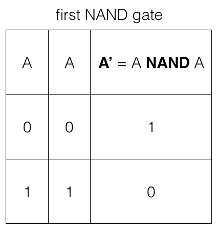
Note! The first NAND gate takes A as both the input so, we have two input options.
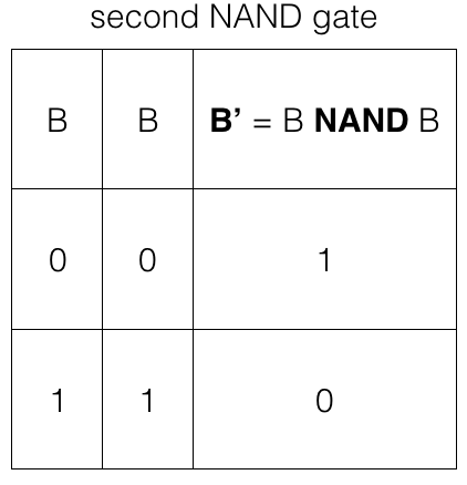
Note! The second NAND gate takes B as both the input so, we have two input options.
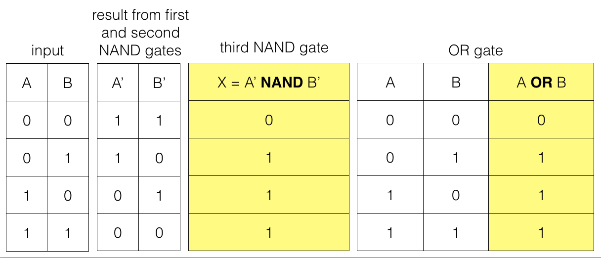
Note! The third NAND gate takes A' and B' as input so, we have four input options.
So, we have an OR gate result using three NAND gates.
ADVERTISEMENT